
Tactical Data Links.
Elbit Systems Deutschland supports Link 11 and Link 22 with state of the art shipboard and airborne equipment. The Link 22 Operational Management Application (LOMA) enables the design of performant networks with minimal congestion, then mapped into an associated Operational Tasking Data Link (OPTASK LINK) message.
Link 22 Operational Management Application (LOMA).
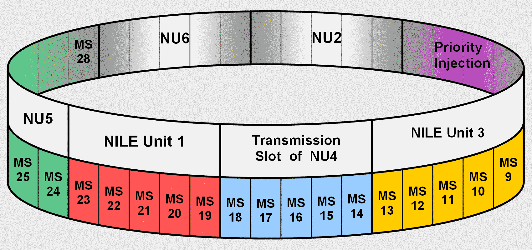
Link 22 allows to operate multiple nets on different frequencies or hop sets, with each net assigned an individual and carefully selected waveform. Gateway units can pass tactical data between nets through their simultaneous membership in more than one network. For each net, Link 22 organizes the data traffic by “Time Division Multiple Access” (TDMA) based net cycle structures. Loma supports the network designer with a structured capture of the network participants and their memberships, roles, attributes and desired data throughput. Communication parameters are defined for network setup. LOMA allows both a preview of the net cycle structures inherent in the system and the alternative computation of optimized and, if required, customized net cycle structures. The full and final set of information describing the entire Link 22 operation can be exported to an Operational Tasking Data Link (OPTASK LINK) message which is read by local Link 22 Data Link Processor applications.
Features
- Import and export of validated OPTASK LINK messages
- Import and export of validated Link 22 segments for integration in a multi-TDL OPTASK LINK message
- OPTASK LINK messages in text format according APP-11(D)
- OPTASK LINK messages in XML format according APP-11(D)
- Preview of net cycle structures if to be calculated by the Link 22 system
- Computation of net cycle structures for maximum throughput
- Manual definition of net cycle structures by subject matter experts
- Beyond line of sight assessments
Options
- USMTF according MIL-STD-6040B
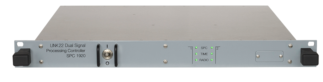
Link 22 shipboard Signal Processing Controller SPC 1920.
The SPC 1920 incorporates two functional Signal Processing Controller (SPC) entities, SPC #1 and SPC #2, providing concurrent dual-network operation for Link 22. Each embedded SPC operates independent from the other one.
This product is discontinued.
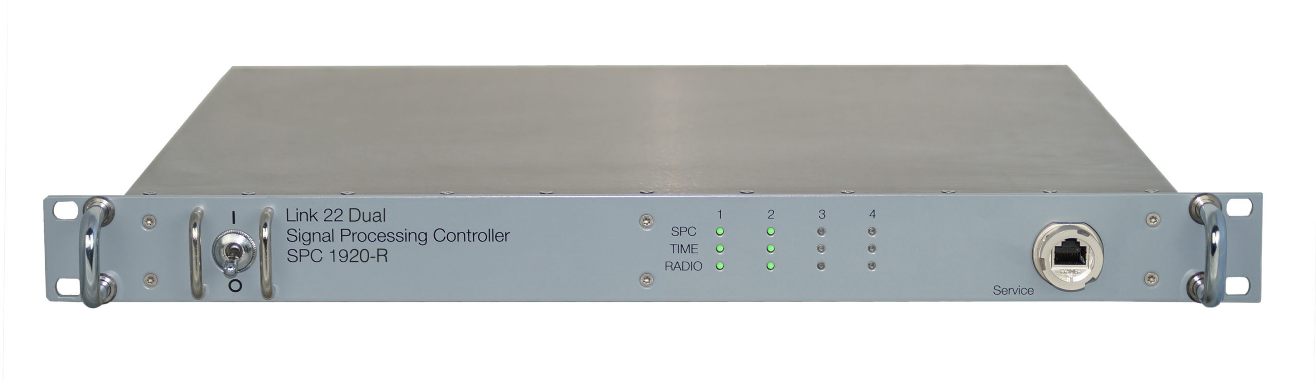
Link 22 shipboard Signal Processing Controller SPC 1920-R.
The SPC 1920-R incorporates two functional Signal Processing Controller (SPC) entities, SPC #1 and SPC #2, providing concurrent dual-network operation for Link 22. Each embedded SPC operates independent from the other one.
Features
- 1U 19 inch rack mount enclosure
- HF fixed frequency (HF-FF) operation
- UHF fixed frequency (UHF-FF) operation
- UHF frequency hopping (UHF-EPM) operation
- Supporting latest NILE block cycle release
- Service interface at front panel
- Environmental conditions acc. MIL-STD-810
- Electromagnetic compatibility acc. MIL-STD-461
HFFF Options
- STANAG 4539 annex E: Traffic waveform 7 and Management waveform
- STANAG 4539 annex F: Traffic waveforms 8–12
- STANAG 4539 annex G: Traffic waveforms 13–18
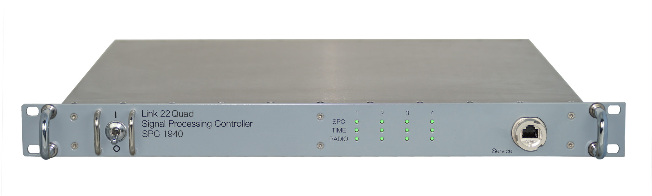
Link 22 shipboard Signal Processing Controller SPC 1940.
The SPC 1940 incorporates four functional Signal Processing Controller (SPC) entities, SPC #1 to SPC #4, providing concurrent quad-network operation for Link 22. Each embedded SPC operates independent from the other one.
HF-EPM mode of operation is ready for implementation but pending due to regulation by the U.S. on TRANSEC availability. A proprietary TRANSEC solution – enabled by relaxed standardization – can be provided on demand but at the expense of violated interoperability.
Features
- 1U 19 inch rack mount enclosure
- HF fixed frequency (HF-FF) operation
- UHF fixed frequency (UHF-FF) operation
- UHF frequency hopping (UHF-EPM) operation
- Supporting latest NILE block cycle release
- Service interface at front panel
- Environmental conditions acc. MIL-STD-810
- Electromagnetic compatibility acc. MIL-STD-461
HFFF Options
- STANAG 4539 annex E: Traffic waveform 7 and Management waveform
- STANAG 4539 annex F: Traffic waveforms 8–12
- STANAG 4539 annex G: Traffic waveforms 13–18
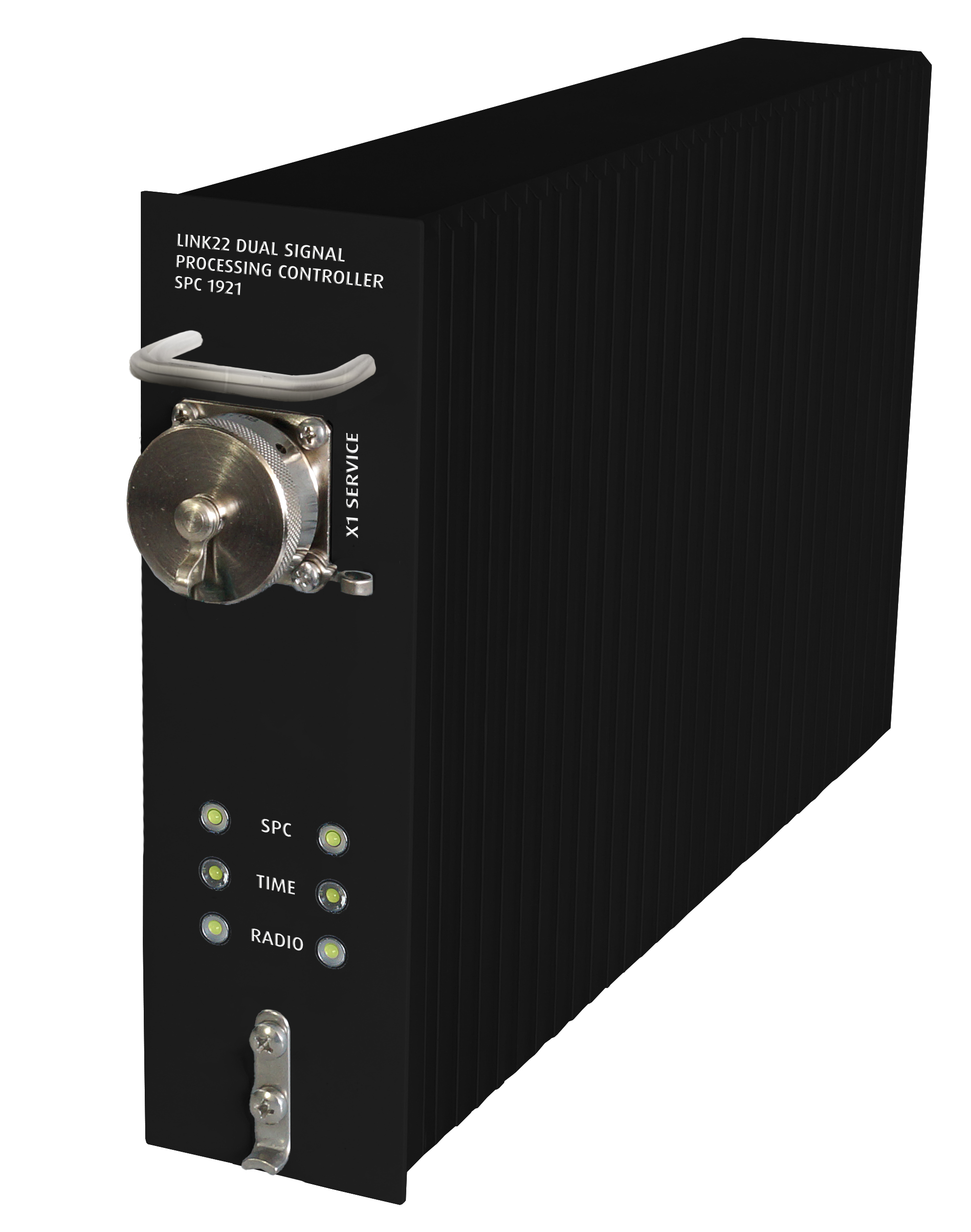
Link 22 airborne Signal Processing Controller SPC 1921.
The SPC 1921 is the airborne version of the shipboard SPC 1940, built by porting the proven SPC 1940 functionality to airborne suitable hardware and power supply. The SPC 1921 incorporates two functional Signal Processing Controller (SPC) entities, providing dual-network operation for Link 22.
Features
- ARINC-600 2 MCU Standard chassis
- Rear ARINC 600 connector
- Front Ethernet service interface
- HF fixed frequency (HF-FF)
- UHF fixed frequency (UHF-FF)
- Supporting latest NILE block cycle release
- Environmental conditions acc. MIL-STD-810
- Electromagnetic compatibility acc. MIL-STD-461
HFFF Options
- STANAG 4539 annex E: Traffic waveform 7 and Management waveform
- STANAG 4539 annex F: Traffic waveforms 8–12
- STANAG 4539 annex G: Traffic waveforms 13–18
MORE OPTIONS
- UHF-EPM mode of operation
- Remote control of radio(s)
- Dual-network operation
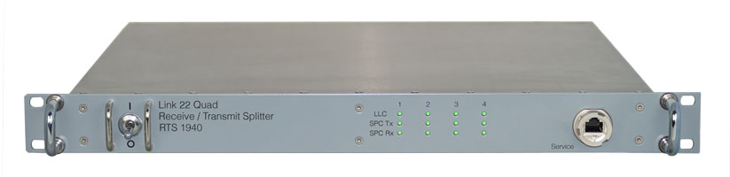
Link 22 Quad Receive / Transmit Splitter RTS 1940.
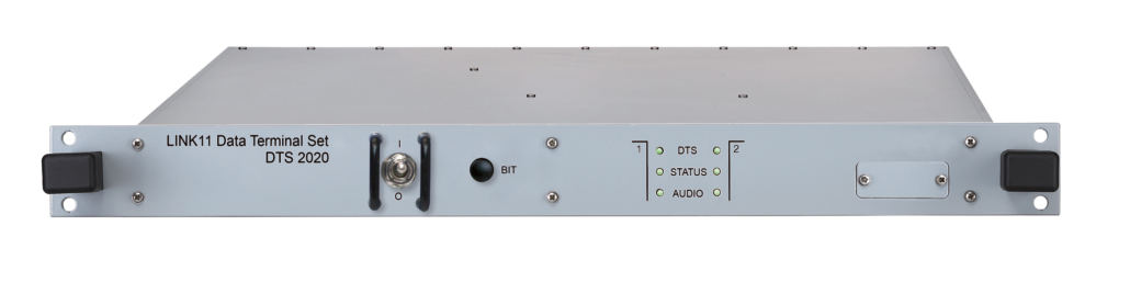
Link 11 Data Terminal Set DTS 2020.
The DTS 2020 supplies all modem and network control functions required in a TADIL-A / NATO Link 11 system as per MIL-STD-188-203-1A. Modulation types are Conventional Link Eleven Waveform (CLEW) and Single-tone Link Eleven Waveform (SLEW).
Features
- 1U 19 inch rack mount enclosure
- Crypto interface: NTDS parallel
- Radio interface: nom. 0 dBm, balanced, 600 Ω
- Control interface: Ethernet
- Power supply: 110 – 240 V AC, 50/60 Hz
- Environmental conditions acc. MIL-STD-810
- Electromagnetic compatibility acc. MIL-STD-461
Options
On demand, optional support is provided for:
- Link 11 over SATCOM
The DTS 2020 relays tactical information to and from a SATCOM modem connected by a digital interface. - Multi Frequency Link 11 (MFL) Operation
Concurrent / redundant transmission of tactical information on multiple HF/UHF frequencies.
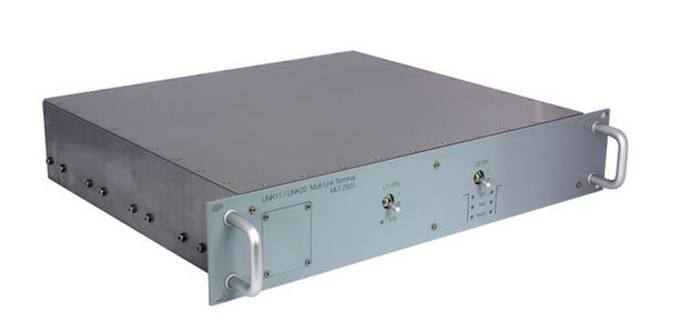
Link 11/22 Multi Link Terminal MLT 2920.
Concurrent multi link operation The MLT 2920 incorporates one Link11 modem (data terminal set, DTS) and two Link 22 modems (signal processing controller, SPC) for concurrent and unrestricted multi link operation. The Link11 modem supplies all modem and network control functions required in a TADIL-A / NATO Link 11 system as per MIL-STD-188-203-1A. Modulation types are Conventional Link Eleven Waveform (CLEW) and Single-tone Link Eleven Waveform (SLEW). Each Link 22 modem supplies operation by either HF fixed frequency (HF-FF), or UHF fixed frequency (UHF-FF), or UHF electronic protection measures (UHF-EPM) communication.
This product is discontinued.
The Multi Link Terminal
MLT 2920 is a 2U rackmount device offering solution for space restricted vessels. All operational connectors are located on the back side. Operator performs initial set to work by service interfaces located on the front side. Product maintenance occurs in place without dismounting. During life cycle user benefits from Link 22 growth potential by uploading new features to the MLT 2920.
Link 11
- Crypto interface: NTDS parallel
- Radio interface: nom. 0 dBm, balanced, 600 Ω
- Control interface: RS-423 async
- Service interface: RS-232 compatible
Link 22
- HF fixed frequency (HF-FF)
- UHF fixed frequency (UHF-FF)
- UHF frequency hopping (UHF-EPM)
- Supporting latest NILE block cycle release
- Front Ethernet service interface
- Remote cotrol of HF/UHF radios by each SPC
General
- 2U 19 inch rack mount enclosure
- Line-Replaceable-Unit (LRU)
- Power supply: 100 – 240 V AC, 50/60 Hz
- Environmental conditions acc. MIL-STD-810
- Electromagnetic compatibility acc. MIL-STD-461
HFFF Options
- STANAG 4539 annex E: Traffic waveform 7 and Management waveform
- STANAG 4539 annex F: Traffic waveform 8–12
- STANAG 4539 annex G: Traffic waveform 13–18